
Pump Demonstrator Project
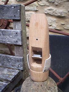
| Here's an excellent full size model of a pump in Yetminster, Dorset, which nicely demonstrates the theory of operation as well as providing some valuable insight into how to make a traditional wooden bucket & clack valve. The project was instigated by retired Civil Engineer Howard Jones, brought to fruition by Chris Bugler and the photos were taken by Deryck Parris. | |
|
|
|
|
|
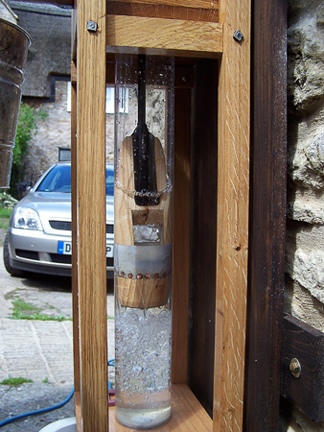
| The wooden
bucket is modelled on an original one that has needed replacing over the years.
It is turned on a lathe and a narrow shoulder produced upon which the leather
seal sits. (The seal is cut away in the photograph for the sake of clarity, so
that you can see the clack valve within.) The upper and lower ends of the
bucket are rounded off so as to accommodate the inevitable degree of lateral
movement away from the vertical when in operation. The upper end of the bucket
is tapered down so as to snuggly fit into the V-shaped end of the iron
operating rod. A wide slot is cut right through the bucket to take the clack
valve, and a hole bored from the underside to meet this slot. The leather clack
valve carries a weight, traditionally lead but iron will do, which can either
be glued on to or bolted through the leather flap. The clack valve assembly is
typically attached to the bucket by means of copper tacks, and the same type of
tack is used to fix the leather seal to the outside of the wooden bucket.
The inlet valve can't be seen in these photographs, but is situated at the bottom of the clear plastic barrel and is probably in the form of a typical combined seal and "C-type" hinged and weighted flap. |
|
 |
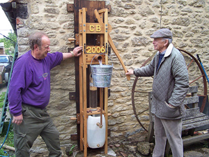 |
| The ingenious assembly is a "closed-circuit" system which pumps water up from the plastic reservoir, out through the spout to the waiting galvanised pail, through the bottom of the pail via the copper pipe and straight back into the reservoir. Very clever! | |